Rehabilitating a 1967 Gibson Lancer GA-35RVT Guitar Amplifier
|
In late 2002, I bought a beat-up Gibson Lancer, serial number A03583, for $182 on e-bay. The previous owner had stored the amp in a workroom, and sawdust had thoroughly worked its way into the cabinet. The fact that the amp had no cover did not help. The amp still had its original straight, ribbed cone CTS speaker, made in the 52nd week of 1965, according to the speaker code stamped on the magnet. The amp had two 7591 output tubes, one made by Westinghouse, the other by RCA, and one output tube socket did not match the other, evidence that one tube and socket had each been replaced. The amp came with two 6EU7 tubes, three 12AU7's, one of which was supposed to be a 12AX7, and an 0A2 gas voltage regulator. Someone had added position marks to the silver anodized faceplate using magic marker. The masonite base of the footswitch was cracked. I decided to try my hand at fixing this amp up, and this was just the start of what led to a lot of information and a pretty nice sounding guitar amplifier. Ugly duckling from Michigan.
Cleanup The first thing I did was to disassemble the amp, and clean and repair the basket-weave style tolex covering the cabinet. Stubborn dirt, paint, and bits of food and other tenacious gooey stuff had worked their way into the depressions in the weave pattern, so I had to use various cleaners, solvents, and brushes. I touched up a few gouges with a black vinyl repair kit from the local auto parts store, and I used some Testors black gloss enamel paint on the scuffs. I used contact cement to tack down a couple of sections of the tolex that had started to peal away from the cabinet. I also cleaned the footswitch and repaired its cracked masonite base with wood glue and clamps. I removed the faceplate and carefully covered it with an old T-shirt. Then I placed it on my workbench and gently banged out some of the dings in the bottom edge with a small ball-peen hammer. Next, I went to work on the magic marker lines with Q-tips and paint remover. In one spot, I accidentally dissolved the edges of some of the original lettering, so I bought some Datek dry transfer letters and fixed the smudges. I used a toothpick and some black paint to repair some of the letters that had scratches across them. Then I soaked the faceplate in warm water with a mild detergent as a final cleaning. The numbering on the knobs had long ago gotten rubbed off, and restoring the knobs proved a challenge. I decided against replacing the knobs. The knobs from the white-panel Gibson amps resemble readily available Fender knobs, but they are push-on, not setscrew, and slightly smaller in diameter. I scoured the internet and visited several surplus stores over a period of several months, but I could not find suitable replacements. First I tried painting the numbers on by hand, but the embossed depressions on the knobs that outline the numbers proved too faint and insignificant to guide my clumsy little fingers and paintbrush. Eventually I settled again on Datek rub-on lettering, available with numbers almost exactly the correct size for these knobs. I finished the knobs off with a light coat of clear protective lacquer, which I had to apply in very thin coats to avoid dissolving the numbers. I removed the speaker baffle, speaker, and grill cloth. Between the bottom of the speaker and the grill cloth, I removed about two tablespoons of sawdust. I wonder how this affected the sound? I soaked the grill cloth in the bathtub in a mild solution of Pine Sol for several hours. I also tried bleach. Lots of dirt came out of the grill cloth, but I could see that the white plastic threads in the weave had aged to a dull beige. The sections of the grill cloth around the edges of the baffle looked shiny and new compared to most of the grill cloth. The grill cloth also had a small tear in it that I thought I could repair using small threads taken from the edge. I had planned to bridge the tear with threads attached using Super Glue, but I knew that this would be a time consuming job. In the end, I replaced the grill cloth with a new piece of Fender black & silver grill cloth. The baffle board had been dyed black, not painted, and some of the dye was coming off on my hands during all this, so before replacing the grill cloth, I applied a light coat of Krylon flat black spray paint to both sides of the baffle. Inside the Amp Now on to the electronics. I have assumed that the reader has a basic understanding of tube amps and can more or less read a schematic. Like most old tube amps, this one consists of a high voltage power supply, for each channel a tube preamplification stage, a tone stack with volume control, and then a recovery amplification stage. The two channels come together in a tube mixer, then the signal goes to a phase inverter, and then to a push-pull power amplification stage and to the speaker. I have left out the tremolo and reverb in this description.
Along with removing the "death cap" and replacing the two-prong power cord with a beefy three wire cord to bring the amp up to modern UL safety code, I added a short terminal strip and spade lugs to the end of the power cord for strain relief. This made wiring the new power cord a little easier and neater. I found a replacement for a broken 2-prong accessory jack in a surplus electronics store, and I wired this to the terminal strip. I had hoped to add three MOV's (surge suppressors), but I could not find enough room for these and decided to the amp did not really need them. One power supply filter capacitor, a big paper and wax dual 20 mF unit, had an ominous bulge in it, so I replaced this and two other paper and wax filter capacitors. I used a multi-section JJ 20x20x20x40 can capacitor to replace the two dual capacitors, and a Sprague Atom 20 mF to replace the third, single capacitor. I built a small right-angle aluminum bracket to mount the JJ rather than drill a large hole in the chassis for the JJ, the black cylinder in the picture below.
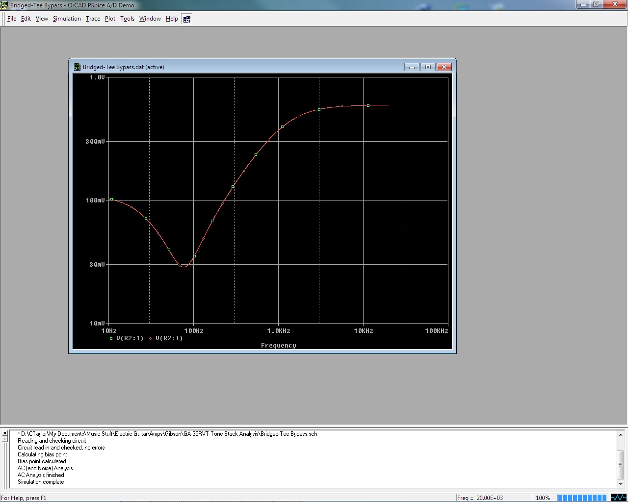
Next, I added a DC bias circuit to the heater lines to reduce hum. This consists of a voltage divider, 1.1 meg made up from a 1 meg and 100 k resistor in series, connected from the high voltage B+ to ground. I connected the center tap of the heater filament transformer to the junction of the 1 meg and 100 k resistors. I also added a 47 mF capacitor from the junction to ground to reduce potential hum. This cicuti adds a 41 volt DC bias to the 6.3 VAC heater voltage. The amp also got a new set of twisted pair heater lines, which I pulled up and away from the tubes to reduce hum, and some nicely routed and tied cloth wires to replace the sloppily routed high voltage lines. I replaced the old screen grid resistors with two compact 10 watt ceramics. The old resistors, which did not match, had been suspended in mid-air atop a rat's nest of messy wiring to the output tubes, and they had presented a risk of shorting. While I was working on the output tubes, I installed two new metal tube retainers clips. One was missing, and other was too small in diameter and incompatible with the bases of the new 7519EH tubes that I had purchased. I added a 10 k bias potentiometer to the output tube bias circuit. By adding a couple of resistors in parallel to the 47 k to ground, I was able to reduce this value to 37 k, so that the total still came to 47 k (10 k + 37 k). I spent some time checking the resistors and discovered that most of the 220 k resistors were more than 10 percent high, typically 240 k - 250 k. I replaced these (reverb in, reverb return, V5A grid). I also replaced the 4.7 k cathode bypass resistor on V4A, which had read 5.17 k. I polished and gloss lacquered the tube shields. New, shiny ones are available for a few bucks each, but cleaning the old ones was more fun. I cleaned the transformers and the top of the chassis with metal cleaner to remove oxidization and corrosion, and sprayed almost everything with gloss lacquer. I did not spray the laminate or winding sections of the transformers for fear of causing damage. The chassis is a carbon steel that did not take a polish too well, and it will eventually oxidize again. The true fanatic would strip the chassis and have it chrome, gold, or brass plated for protection, but I doubt this amp is worth that much effort. I began to reassemble the amp and managed to punch three holes in the speaker with the screws sticking out of the baffle. This was a real amateur move. I repaired the speaker by patching the holes but I knew that I would be getting the speaker reconed or replaced. Before installing the chassis, I tacked a metal screen to the underside of the top to reduce hum. Old Fender amps typically have this screen, but this Gibson had no screen when I received it, and I saw no evidence that it had ever had one. I moved the chassis back 3/4" to place the front of the control panel directly over the speaker baffle. These amps as originally made commonly had the chassis protruding and overhanging the top of the speaker baffle by about an inch. This looked weird and allowed the knobs and faceplate to get damaged easily, particularly in the event that someone or something knocked the amp over. Basic Mods I fired up the amp and discovered that it had a very bright sound, bordering on shrill, unless I turned the treble way down. The amp also had a pronounced midrange notch. The amp started to break up nicely at about "7" on the volume dial, at which point it was loud but not deafening. The midrange notch made it sound good with my distortion pedals, but I was not crazy about the brightness of the amp. I improved the sound somewhat by replacing the cathode bypass capacitor in the first preamplification stage of the Reverb channel across V1B with a 20 uF capacitor instead of 5 uF. This boosted the bass a bit and made the amp sound a little bit more like an old Fender. Before I was done, I had increased the bypass capacitor in the second stage preamp from 1 uF to 11 uF (V4B), and the bypass capacitor in the third and final stage (V5A) from 2 uF to 8.8 uF. At one point I had the final stage up to 35 uF, but this hyped the bass too much. After installing a new speaker and using the amp for a few weeks, I later decided that it really had too much bass, and in any case sounded pretty much the same as my other (modern) amps. Why not restore it to its original tone as nearly as possible, and be able to take advantage of its unique tone when needed? This seemed like a good plan. While I was at it, I decided to fix the metallic sounding reverb. To do this I would probably need the correct schematic. Schematic & Circuit Details To make a long story short, I worked on the amp off and on for a couple of months and posted my results. Over a period of several years, other Lancer owners contacted me with questions, observations and additional information, and I was able to get my hands on the correct schematic. The first thing I learned was that there were at least two versions of this amplifier on the market. The first (apparently) was the 12-65 circuit (I assume drafted in 1965). This is the version that I have, which appears to be the most common version of the amp. The second version, 12-66, is the most commonly available schematic on the internet, but this amp appears to be much less common than the 12-65 version although by no means rare. The 12-65 version uses a 12AU7 in the second preamp tube position (V4A and V4B). Substituting a 12AX7 here results in a very bright, even ice-pick-like tone, as I discovered. After mucking about with the treble and bass tone stacks and trying the standard blackface Fender stack and a Baxandall-style Ampeg tone stack, I realized that the tone stack in the Lancer is quite simple and has very low insertion loss, pretty much along the lines of the Fender Tweed-era tone stacks. One cannot substitute the Fender of Ampeg tone stack without compensating with higher gain in the preceding or following tube stages, and this would probably require adding AN ADDITIONAL tube amplification stage. The treble control in the 12-65 is a simple high-frequency capacitor that dumps treble to ground. This is pretty simple but it works. The bass control is another story altogether. It took me quite a bit of experimenting, measuring, web research and Spice simulation to finally figure out how the bass control works. It is a bridged T circuit, technically the same topology as a Wheatstone Bridge. With the bass control all the way up, the low (bass) frequencies pass through the circuit almost unhindered, but the mids around 580 Hz are dumped to ground, creating a very severe mid notch. The mid notch is much deeper than in the typical blackface Fender tone circuit, and the Lancer sounds somewhat similar to a blackface-era Fender Deluxe Reverb amp, but with much reduced mid frequency sound, almost a hollow sound. As one turns the bass control down, something odd happens; the frequency of the notch drops. At "0" bass, the notch is around 70 Hz, effectively cutting the bass frequencies but boosting the mids. This could be considered an improvement, but with no bass the amp sounds too thin at this setting. With this particular bass circuit, it is almost impossible to find a setting that sounds good. The 12-66 circuit uses the same treble control, but a more conventional bass control that allows low frequencies to pass or dumps them to ground. To get the carved out mids, the amp adds a fixed-frequency bridged T set to 580 MHz (one for each amp channel Normal, Reverb). The amp adds an additional bridge T downstream just before the phase inverter. I have not tried a Lancer with the 12-66 circuit, but I bet that this version of the amp has no mids at all, and probably vanishes from the mix in a live situation. Other than the bridged T differences, the 12-65 and 12-66 are almost identical, except that the 12-66 uses a 12AX7 instead of 12AU7 in the V4 position, plus some slightly different cathode bias and plate resistor values around V4 that seem to help tame the brightness when using a 12AX7 here. First order of business once I sorted out the correct schematic was to return the values of the cathode bypass capacitors on the preamp tubes (Reverb Channel V1B, V4B, V5A) back to stock according to the 12-65 schematic. More About the Bridged T The bridged T circuit in the 12-66 consists of a 330 pF coupling capacitor in parallel with two 220 k resistors, with a .047 mF capacitor to ground between the two resistors. The version in the 12-65 combines the twin tee with the bass potentiometer. The bass control potentiometer has a tap at the midpoint, plus a 330 pF coupling capacitor across the in and out leads. The tapped potentiometer forms a combination of a bridged-T and the simple high pass bass control shown in the original schematic. Bridged T bass control at '0" (note notch at around 70 Hz). With the control at "10," the notch moves up to 580 Hz, boosting the bass but cutting the mids.
The mid notch caused by the bass control of the 12-65 Lancer with the bass up all the way can be reduced to more sonorous levels by inserting a 50 k trim pot between the .047 uF capacitor and ground. I adjusted this trimpot while playing the amp, and found that 36 k gave the amp just the right amount of mid notch, something similar to the classic Fender sound. For frequency response equations for the bridged T, see Bridged-T. If you have the 12-66 version of the amp and feel that it lacks mids, try this: Do the simple modification described above to the fixed-frequency bridged tee, and then bypass or remove the second bridged tee where the two channels mix together. I bet this will dramatically improve the tone. Mixer The Reverb Channel of the 12-65 version of the amp goes through V4B and then through a 220 k resistor to the mixing stage. The Normal Channel goes through V4B and then through a 1 Meg resistor to the mixing stage. If you want more volume on the Normal Channel, decrease the value of the 1 Meg resistor to 750 k or less. Reverb The reverb had a lush but metallic sound. Somehow the driving signal was leaking into the final output of the amp with a sort of a microphonic feedback sound, even with the reverb turned down to "0." Turning the reverb off with the footswitch was the only way to eliminate this sound bleed problem. I replaced the out-of-spec 220 resistors in the reverb circuit, and this helped quite a bit, but did not entirely cure the metallic sound. To remedy the strange sounding reverb, I examined the circuit used in most of the old Fender amps. I could see that Gibson controlled the volume of the reverb by changing the input level to the first reverb driver tube, while Fender controlled the volume of the reverb by changing the level of the output of the last tube in the reverb circuit. To change the Gibson to approximately the same circuit I did the following:
The reverb now sounded much better, and no surprise, much more Fender-like. However, there remained an important difference in the reverb circuit compared to black face era Fenders. The input to the reverb circuit is picked off from the preamp signal chain before the amplifier's volume control. This means that as you turn the volume of the amp up, the reverb does not get louder. Compare this with BF Fenders. In the old Fenders, the input to the reverb circuit originates after the volume control. As you turn the volume of the amplifier up, the guitar gets louder, and so does the reverb. The circuit in the Gibson could be changed, but this would require major surgery, which would probably also have to include major surgery to the finicky tremolo circuit, which shares a common output with the reverb circuit. I decided to live with this peculiarity of the reverb. The reverb tank in my Lancer appears to be a Gibbs "C" equivalent to an Accutronics 4FB2A1B. The part number translates to long (16.75") two-spring unit with input 1,475 ohms, output 2,250 ohms, medium decay (1.75 to 3.0 sec), input and output grounded at the tank, no lock, horizontal, open side down. Tremolo The tremolo was a little weak on this amp initially, but tweaking the gain adjustment pot on V5B inside the amp helped. I tried a replacement tremolo opto-coupler built out of Radio Shack parts: (1) Radio Shack 12 volt 25 mA bulb 272-1141, and (2) the largest CdS photocell in the five-pack assortment 276-1657. The part number for photocell appears to be P722-7R, but Radio Shack does not sell just one photocell. By placing the bulb and photocell facing each other and then housing them together inside a piece of heat-shrink tubing or the plastic body of a ballpoint pen, you can make your own tremolo roach for this amp. The one I built produced a somewhat weaker tremolo than the stock tremolo roach. I suspect that the voltage rating of the Radio Shack bulb (12 volts) is a little higher than ideal for this amp. Weber VST offers the "OPT-5" roll your own tremolo roach. Either the 12 V or 6 V bulb should work, but I think the 6 V bulb would probably work the best in the Lancer. Speaker The amp sounded particularly nice when running through a Weber VST C10N (10F150) that I had in another amp. Using the Weber, the amp was much louder and less shrill sounding than with the tired old stock CTS speaker. Based on this, I ordered a Weber VST 12F150 speaker (C12N, straight cone, ribbed, ceramic magnet). This really opened up the bottom end of the amp, reduced the shrillness, and improved the loudness. With this speaker, the amp gives my Frankenstrat project guitar the snap and presence that you can hear on Mark Knopfler's "Sultans of Swing" and "Down to the Waterline" (Dire Straights). The amp also sounds great with a Tube Screamer driving it, but running a Boss Metal Zone MT-2 into it sounds like mad hornets, not exactly ideal for Heavy Metal. The original 7591 power tubes should be able to produce around 25 - 28 watts out, but the new EH 7591 tubes are basically 6L6 with changed pinouts, so 35 watts should be possible. Larry Schleifer contacted me and said he measured 15 watts out of his Lancer with an 8 ohm load. Maybe you can get more out of the amp if you drive the amp hard enough into distortion. In any case, 15 watts is actually almost as loud as 35 watts, and the amp should be able to keep up with a Fender Deluxe Reverb (Blackface), which comes stock with two 6V6 output tubes and is supposed to produce about 22 watts. Final Touches I made a baffle board to replace the one missing from the rear top of the amp, and I covered it with Vox-style basket weave Tolex. This Tolex has a matte finish and a smaller weave pattern than the white panel Gibsons, but it is not a bad match. The Gibson branded GA-35 RVT's that I have seen all have had straight rectangular upper baffle panels. I saw an Epiphone branded GA-35 RVT with a panel cut with some extra ventilation at the top for the tubes, more along the lines of a Fender back baffle panel. This looked nicer and seemed more functional to me, so I used measurements from the Epiphone for the panel that I made. Epiphone version of the Lancer. Note back panel shape.
I took the amp down to the local upholstery shop and had them make a reproduction of the original cover. I duplicated the original logo by scanning a copy of the logo from a 1968 Gibson green catalog and printed this out onto label stock. I then cut out and removed the outline of the logo to make a mask, peeled off the back of the label stock, and positioned the sheet on the cover. I painted this with white vinyl spray paint. A bit of paint leaked under the label stock, but after peeling the mask off and cleaning up the goofs with a razor blade, I had an authentic-looking Gibson cover complete with logo. At least from a foot or so away . . . Any closer than this and you can see the imperfections in the lettering of the Gibson logo. Final Comments This amp was somewhat difficult to work on, not as tidy inside as the Fender amps from the same era. It uses point-to-point wiring with a very small fiber board that crams most of the components into a small area near the tubes. The fiber board uses metal well eyelets that capture solder and keep it from pooling underneath and causing shorts, but the board is a regular snake-pit of thick, cloth and plastic insulated wire. Half the components hide behind others on very short leads. The power supply (rectifier / power transformer) area uses two terminal strips, and this area is much easier to work on. Schematic for the finished amp, including modified reverb circuit, in PDF format. If you know how to read a tube amp schematic, most of what I have described above will make sense I hope. Thanks to Phil Symonds, John King, Phil Firano, JD, Tim Gagan, and Mike F from alt.guitar.amps for their suggestions for this project. Also, thanks to fellow Lancer owners that contacted me for help and offered information about their own Lancers: David Wallman, Dave Hilts, Eric O'Brien, Brent Johnson, William Booth, Lance McLaughlin, Holten Kaiser, Peter Mathison, Brian D. Malman, Greg Marten (Murrow's Boys), Simon Delaney, Mark Schraad, Ronald Wisecup, Rob in Chicago, Fred DiFrancesco (owns a Minuteman GA-20 RVT, almost the same as the Lancer), J. Eggers, and Larry Schleifer. This could be a substantial fraction of the Lancer owners still out there! According to Bj—rn Anger, Gibson produced 2,322 of the GA35-RVT amps (see superiormusic.com). I doubt more than half of them are still in existence, but who knows? See also the Gibson Garage at http://www.0rigami.com/gg/amps.html . David Wallman sent a Gibson Service Manual from 1964 (warning, LARGE file, about 149 MB!). This contains a wealth of schematics for Gibson amplifiers of the mid-1960s including the GA35-RVT Lancer and many other old Gibson amps. Some are considered gems, some dogs, but I believe that almost all have the potential to sound great with a little tweaking. The finished amp, still with original speaker:
|
|
?? Visitors since January 1, 2003. |
Optimized for 1024 x 768 display |