Guitar Pedalboard Project
As a result of never having enough room on my board for stomp boxes, I decided to build two boards, one for amp channel switching & MIDI and one for conventional pedals.
I started with the following design goals assuming a left board for MIDI control and a right board for conventional pedals:
Locate all power supplies remotely, away from the pedals, to reduce hum.
Run only low-voltage DC and AC to the boards.
Hide interconnect and power cables but allow easy enough access for repair and temporarily patching in replacement pedals in case of emergencies while gigging.
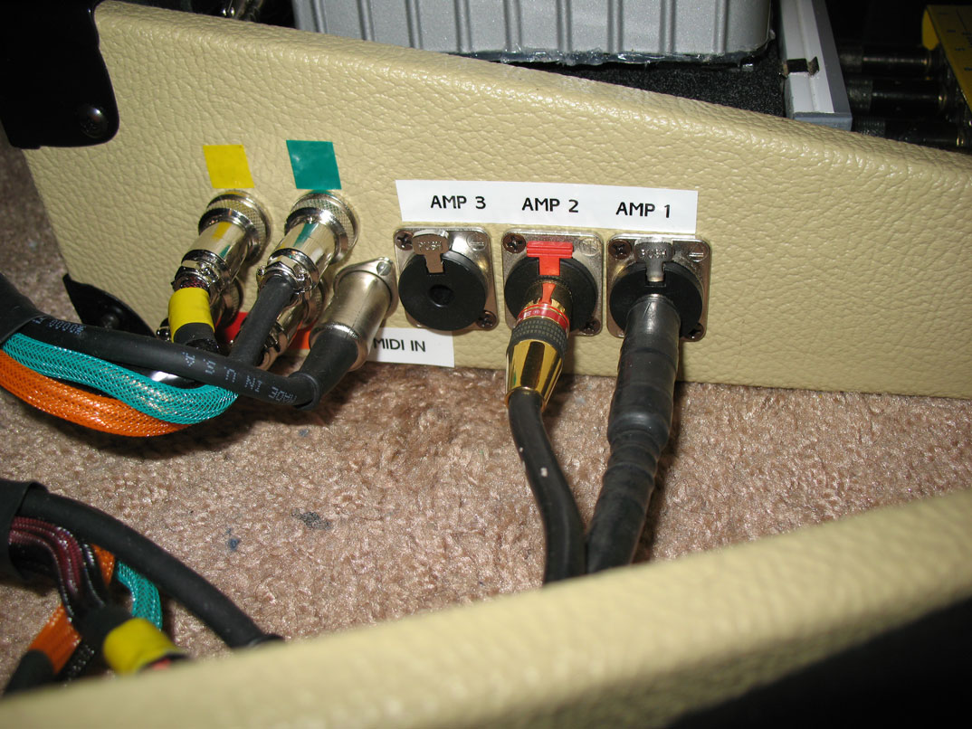
Provide three selectable amplifier outputs with the option to run two of the amps in stereo from rack effects later.
Interconnect the boards for power and MIDI, but install connectors to allow the non-MIDI board to be used independently if desired.
Place "always on" pedals (buffers etc.) on the underside to save space.
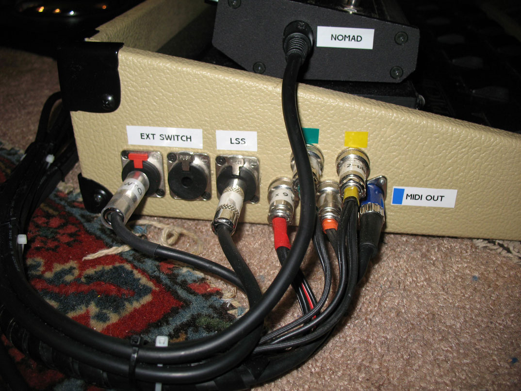
Provide external connectors for 9 VDC and MIDI OUT for adding pedals external to the boards.
Use LED strip lighting for illumination, but only if this can be done without generating audio noise.
Do a NEAT job!
Here are some pictures of the pedalboard project illustrating some of the highlights of the build process.
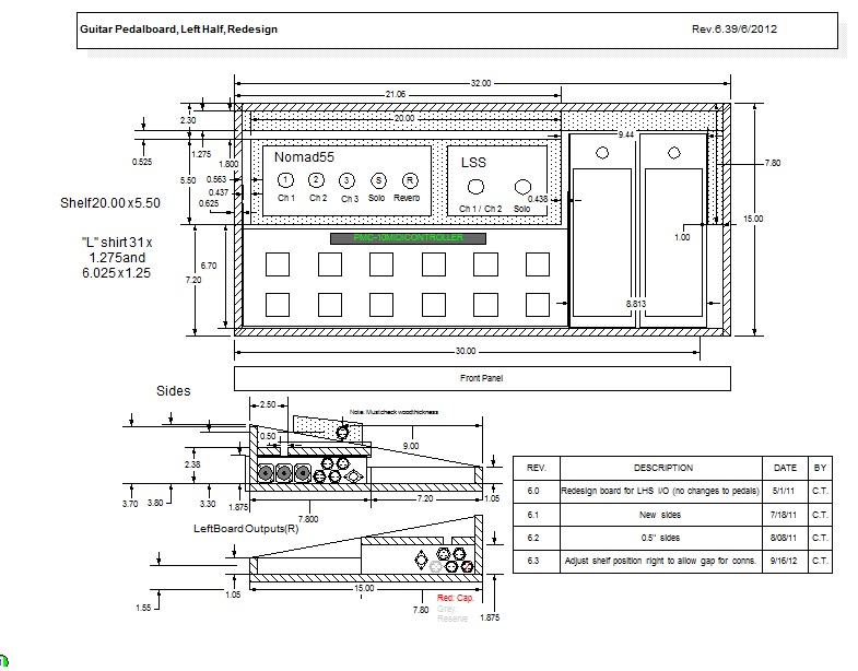
I started with detailed plans based on the pedals I owned and the layout from my existing relatively crude pedalboard.
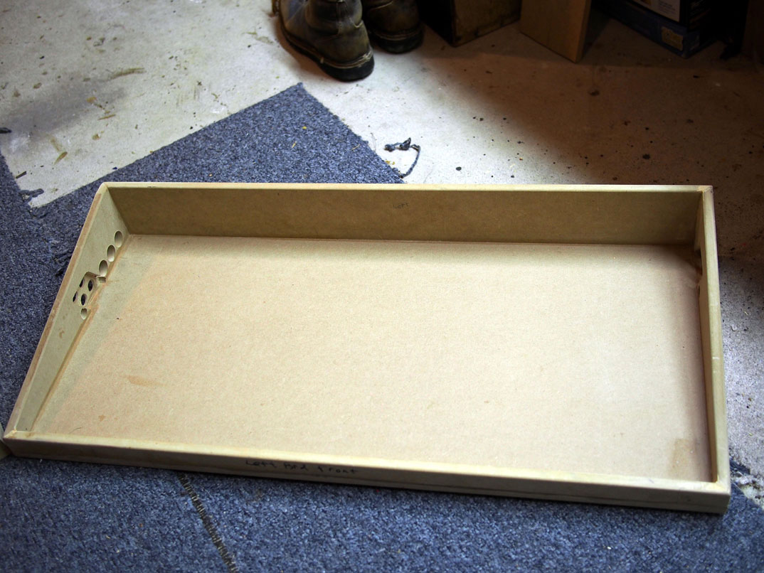
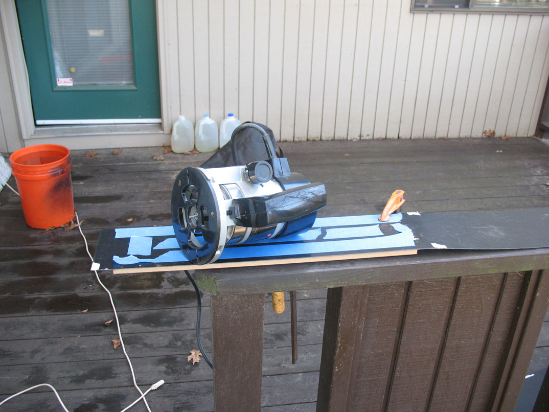
First step after drawing up the plans was to buy and cut 1/2" fiberboard (MDF), and begin gluing the basic LEFT and RIGHT pedalboards together. I used a Freund 40 TPI fine cut blade and a handheld 7.5" power rotary saw for this, plus a cutting guide and lots of measuring and trial cuts. A friend helped me with his table saw for some of the tricky angle cuts at the corners. I used forstner bits to cut holes for the connectors and an inexpensive router to cut the recesses.
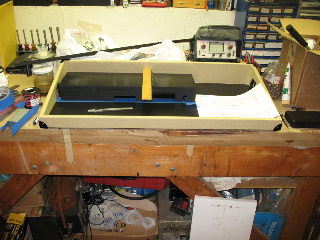
Because of the difficulty putting screws into MDF without it splitting the stuff, I used 1/4" dowels and Titebond 1 glue to connect the pieces. The LEFT board:
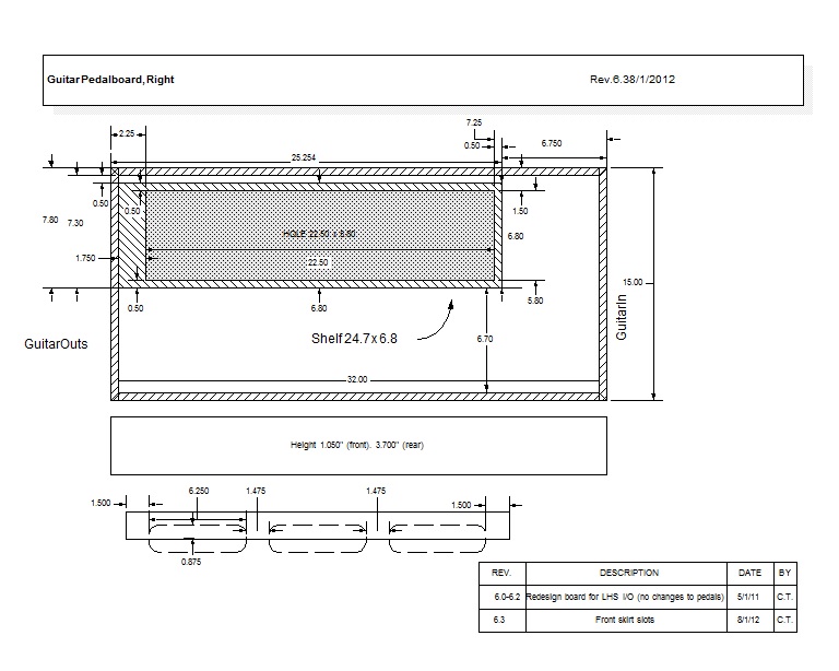
The RIGHT board:
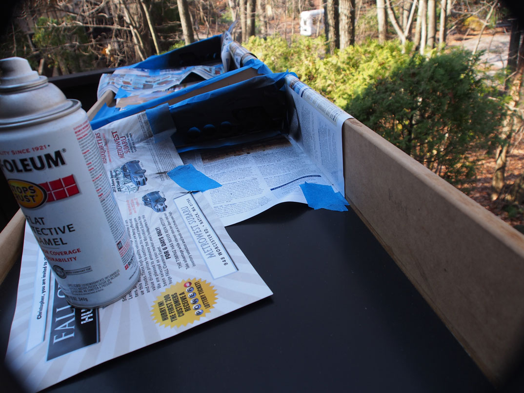
After assembling the basic boards, I purchased some black ABS plastic "laminate" (it really isn't) from Reliable Hardware and carefully cut and glued pieces of ABS onto the right and left board tops using 3M spray adhesive. Next I masked off and sprayed the recesses flat black.
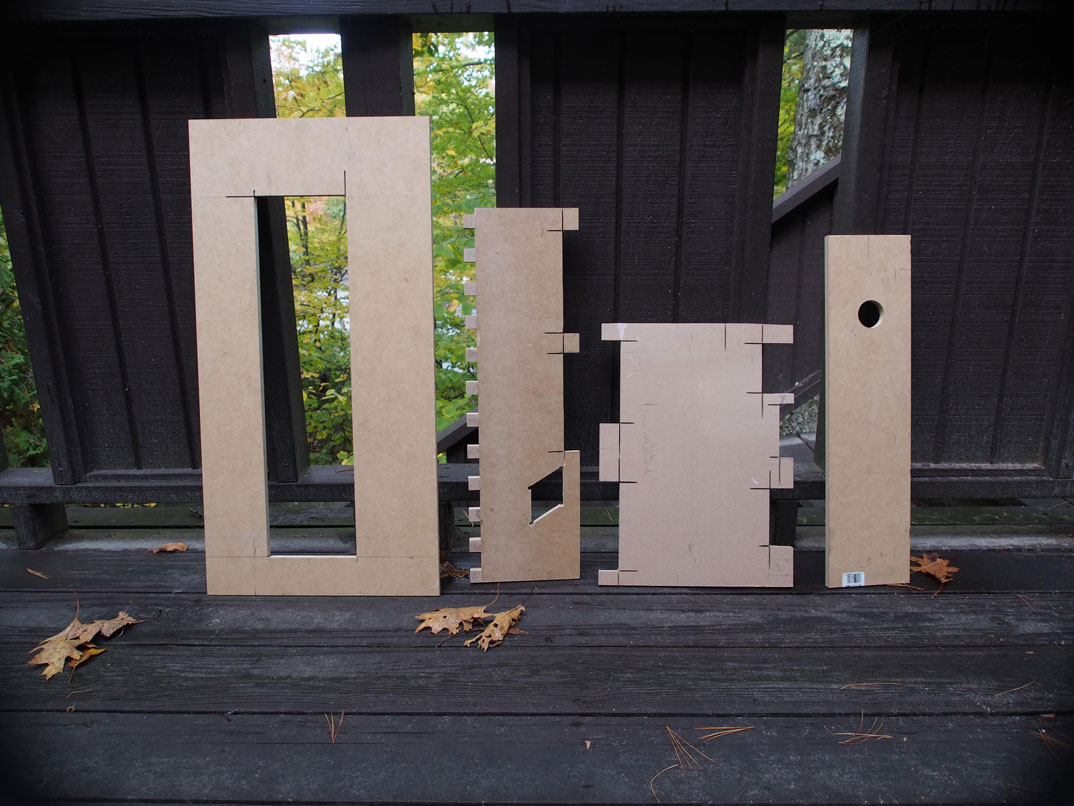
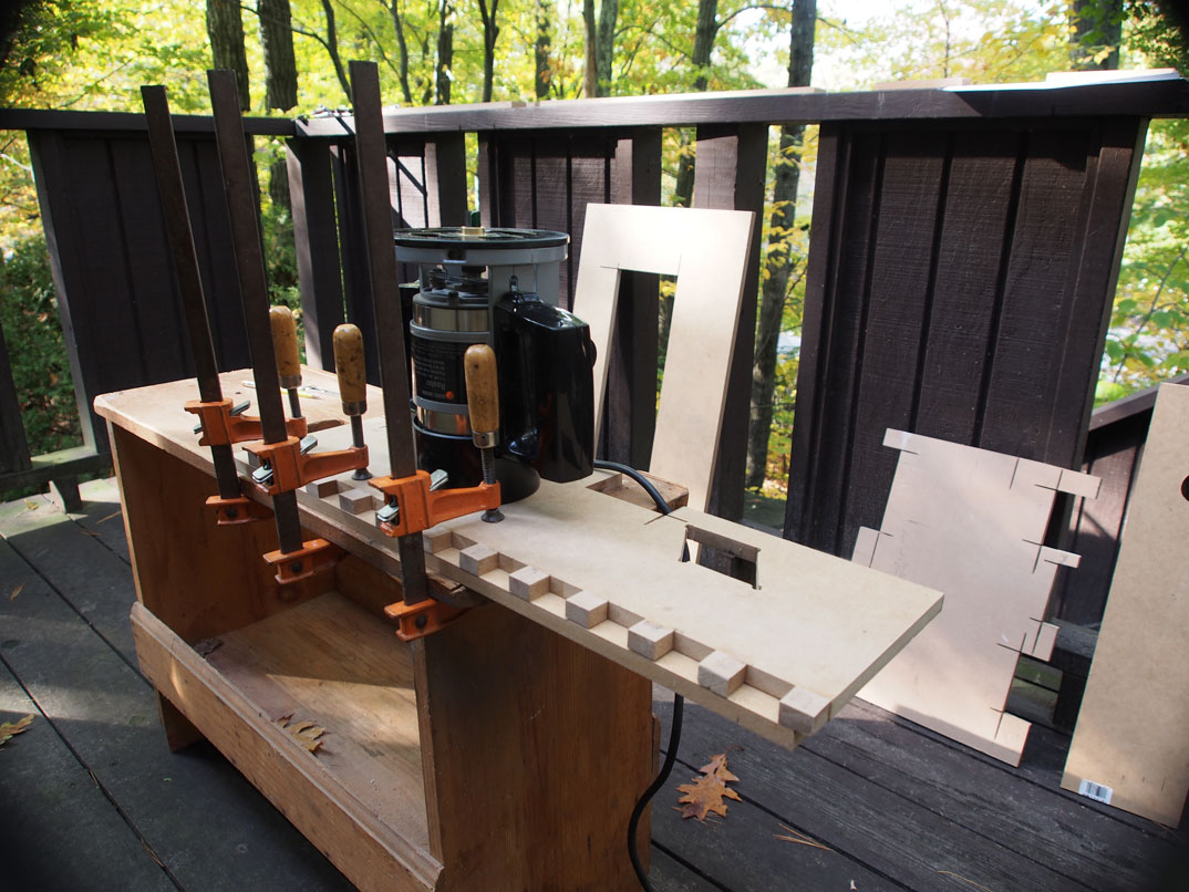
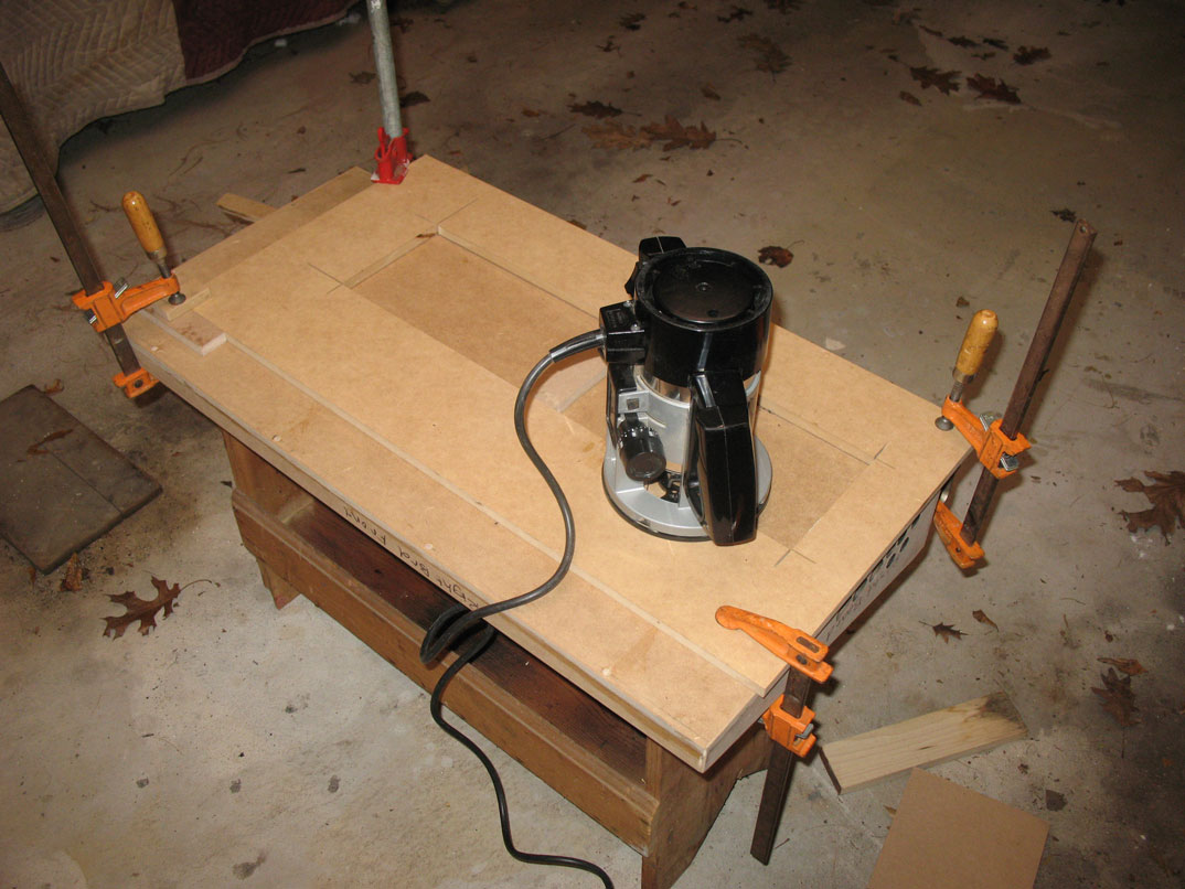
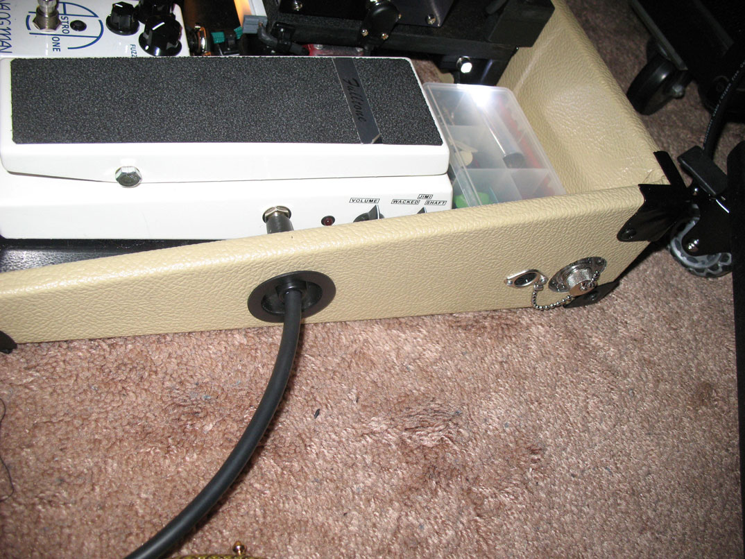
The boards would each have a second tier, or shelf, in the back to put some of the pedals higher than others and to hide the wires underneath. The shelves also provide space underneath the boards for various MIDI boxes and a power supply filter-regulator to convert split-phase AC to bipolar 9 VDC (plus 9 V and minus 9 volt). I use clean bipolar DC to give my buffers plenty of headroom. The uprights for the shelves need cutouts for cabling, so this requires some carefully designed routing templates. The right board also needs an entry hole for the guitar input patch cable. The right board needs a template for an access opening on the bottom. Router templates:
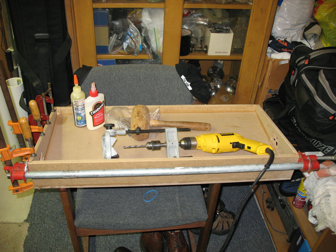
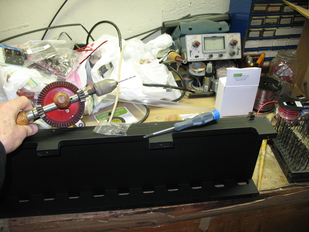
This photo shows a router template set up with my router to cut notches in one of the shelf supports.
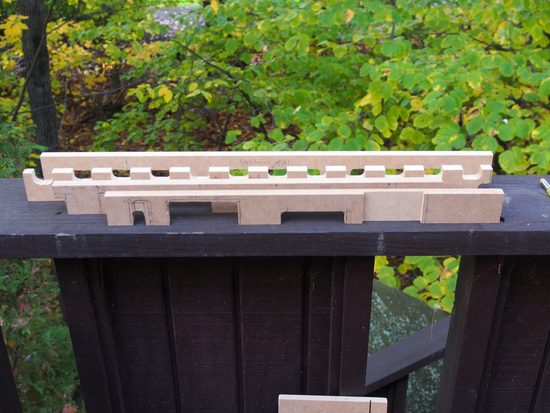
Below, the finished shelf uprights with assorted notches.
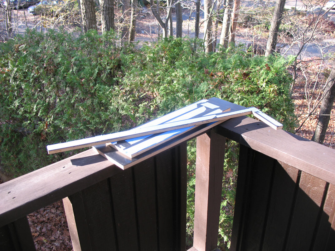
Next I applied ABS to the shelf-tops and to a skirt used to hide cables on the left board, and cut off and smoothed the ABS edges with the router.
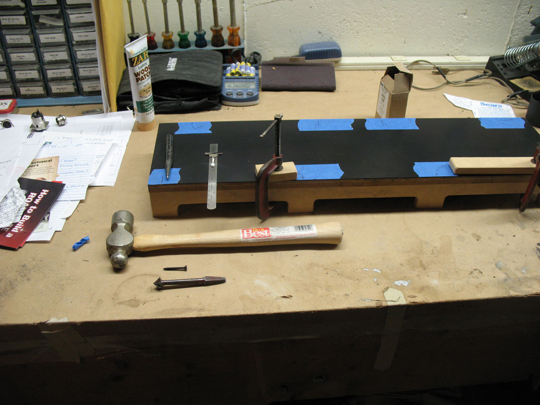
The next step was to screw the shelf for the right-hand board to the shelf supports. I later decided just to use glue, and redid the top ABS piece, eliminating any visible screw heads.
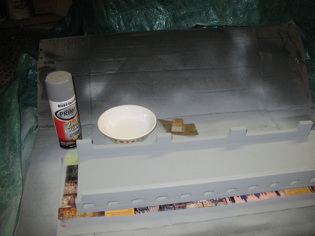
Next I primed and painted the exposed MDF on the edges and undersides of the shelves flat black, with some #400 wet sanding between coats.
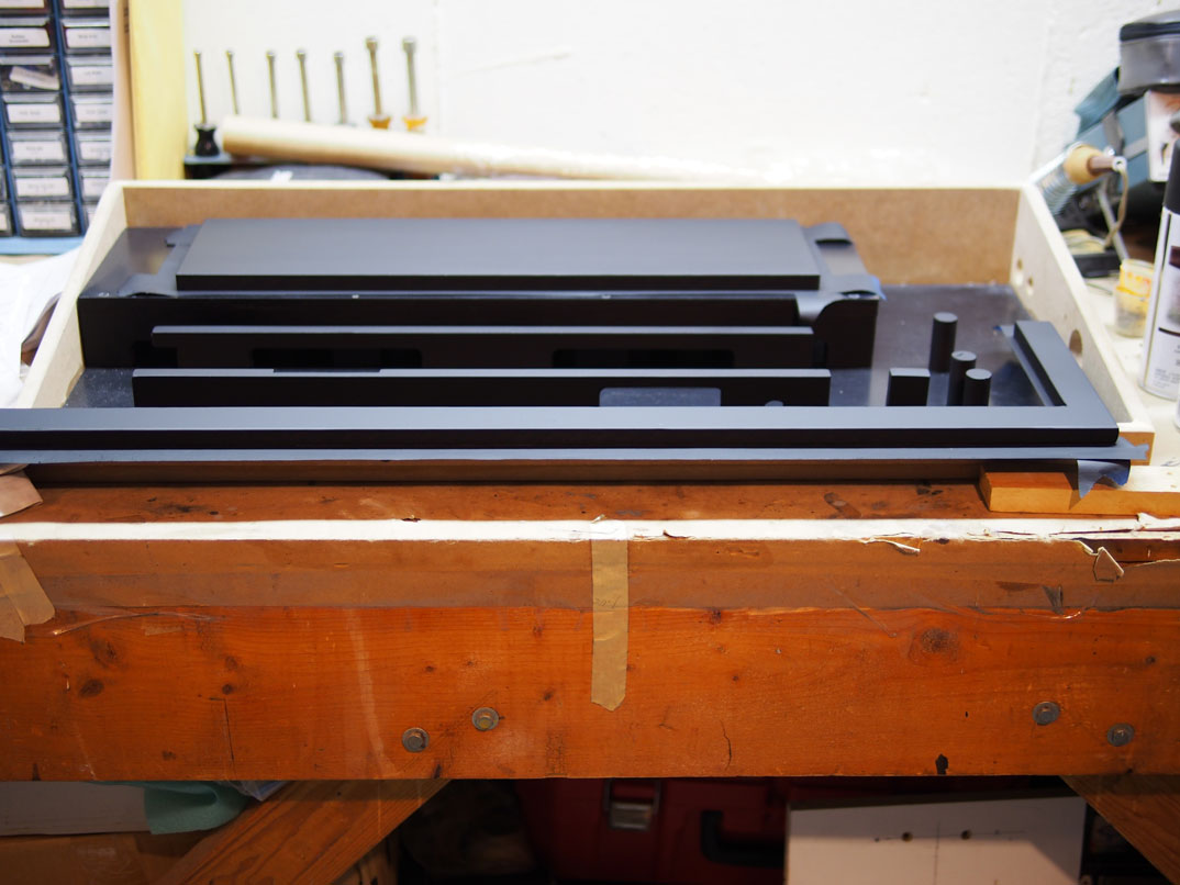
Here is what the shelf pieces look like painted. The round and rectangular pieces on the right have magnets recessed into the tops to hold the skirt (foreground) in place.
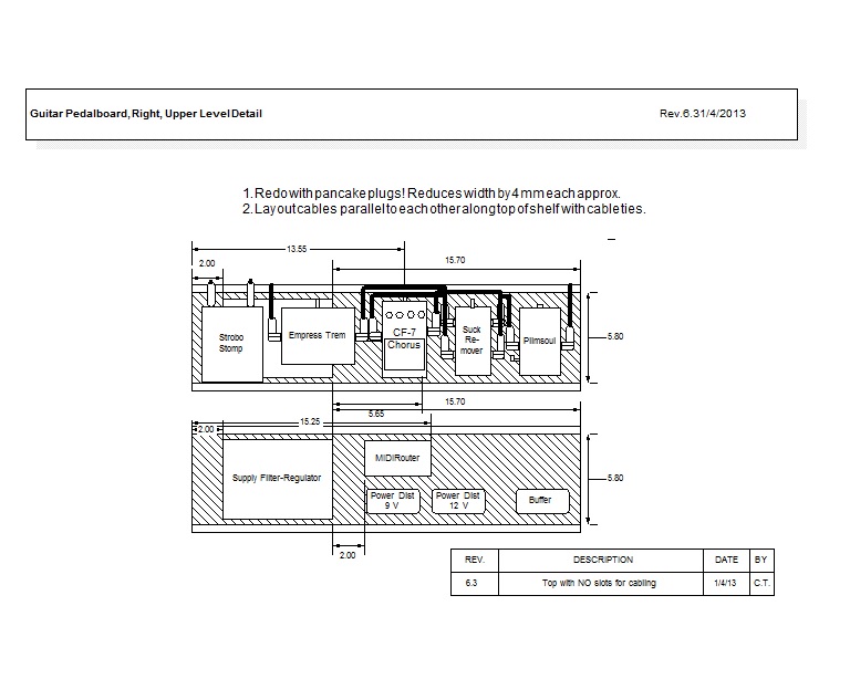
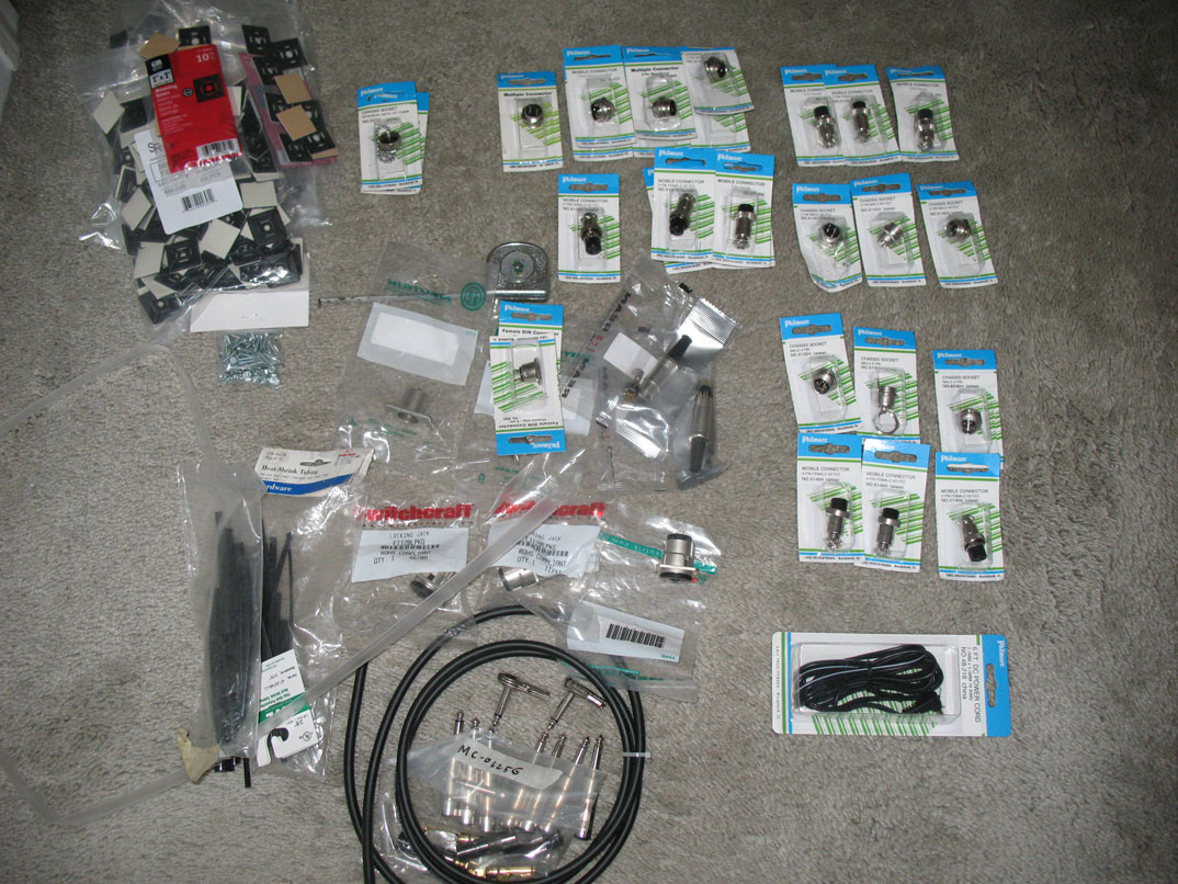
It was a good time to purchase cabling, connectors and cable ties. I purchased low-capacitance cable and low-profile right-angle pancake plugs (1/4" audio) from Best-tronics (guitar-cable.com). Bulkhead connectors came from You-Do-It Electronics.
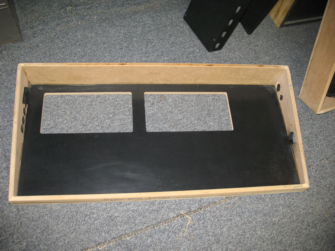
Below, I routed out openings in the bottom of the right-hand board to allow access to the underside of the shelf. This is where I will mount a MIDI router, bipolar power-supply filter-regulator, and power distribution blocks.
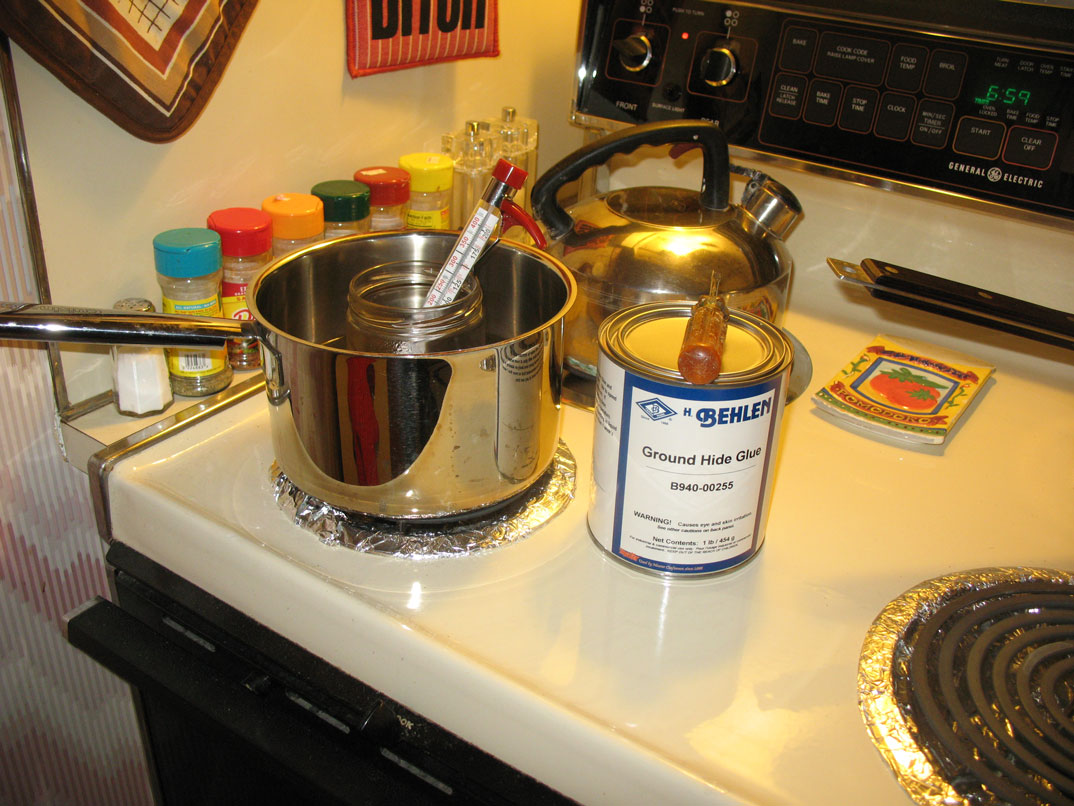
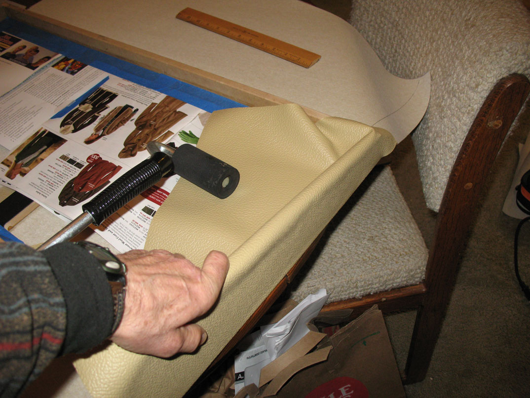
At this point it was time to start applying the Tolex. I chose to use Hide Glue. This stuff turned out to be a real challenge to use. Next time I will use a denser / heavier grade, or will just use a spray-on adhesive such as offered by 3M. Either way, a J-roller is indispensable.
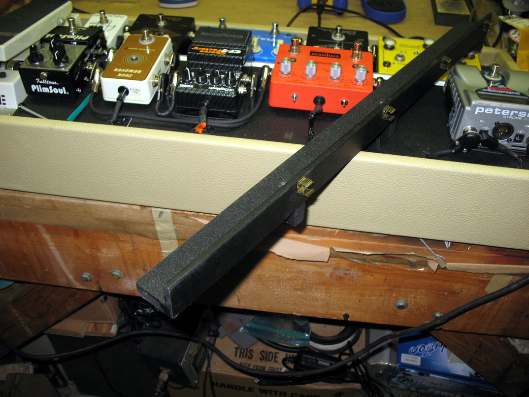
Now it was time to mount the shelf on the left board. This one has hinges to allow access to the underside. Locating the magnetic catches so they would not interfere with the electronics to go under the shelf turned out to be a bit of a challenge. This shelf would be very close to my MIDI foot controller, so it had to have a slim adhesive-backed LED strip along its edge for illumination instead of the ~3/4-inch deep LED bars I used on the right-hand board.
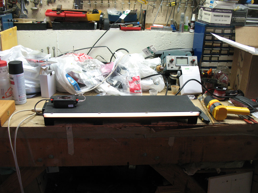
Next I mounted clips on the shelf for the right board for an LED bar with built-in diffuser.
Here is the shelf for the right board with LED bar and LED controller, which will actually go under the shelf of the LEFT board.
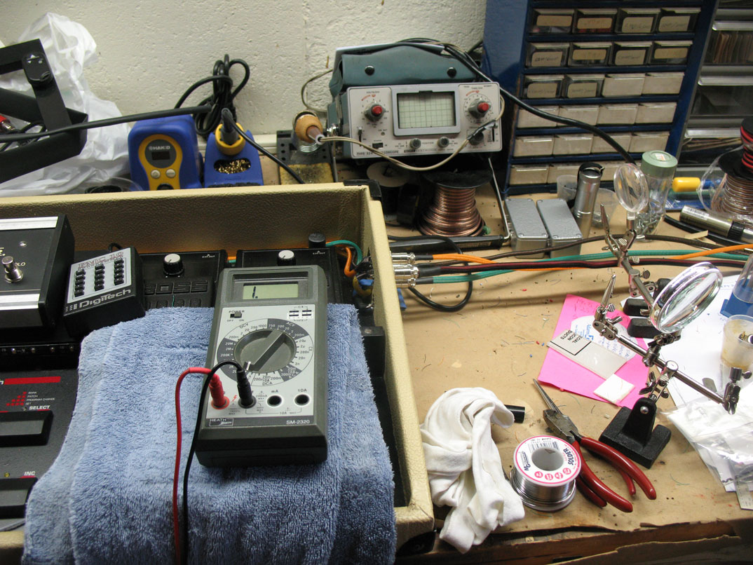
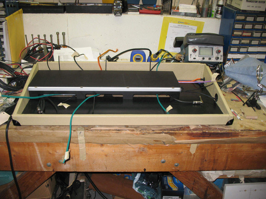
Here I have skipped some steps. I have at this point wired up and mounted all the MIDI pedals on the left board using 3M Dual-Lock. Here I am wiring up the umbilical that will take power and MIDI to the right-hand board, checking continuity as I go.
Here is the LEFT board completed. At this point it was time to wire up the RIGHT board.
The first step for wiring the RIGHT board was to install the Talent Boost buffer, bipolar voltage regulator, MIDI Router and power distribution blocks, wiring as I went. These went on the underside of the shelf unit, then I screwed the shelf unit onto the board from the underside using black finishing washers and black panel screws.
The next step was to mount (with 3M Dual-Lock) and connect the pedals on the right-hand board. Pancake audio plugs take up only 41 mm, allowing you to put pedals close together.
I had planned to use gooseneck white LED lamps for the right-hand board, but I was not satisfied with the lighting or appearance of the one I had, so I purchased another LED strip and put together another LED bar to illuminate the top tier of pedals.
Screwing into MDF is problematic, so I installed some machine screw anchors to hold the top LED bar in place on an MDF riser.
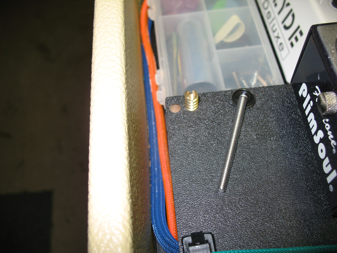
Upper-tier LED riser to hold the new LED bar, MDF and ABS laminate; this will be attached with machine screws:
After triple checking all the wiring, especially the power wiring, I was up and running.
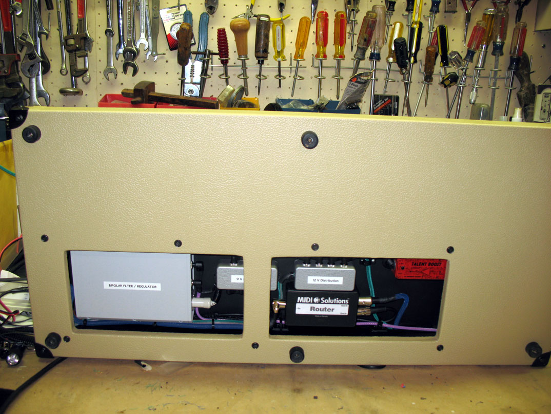
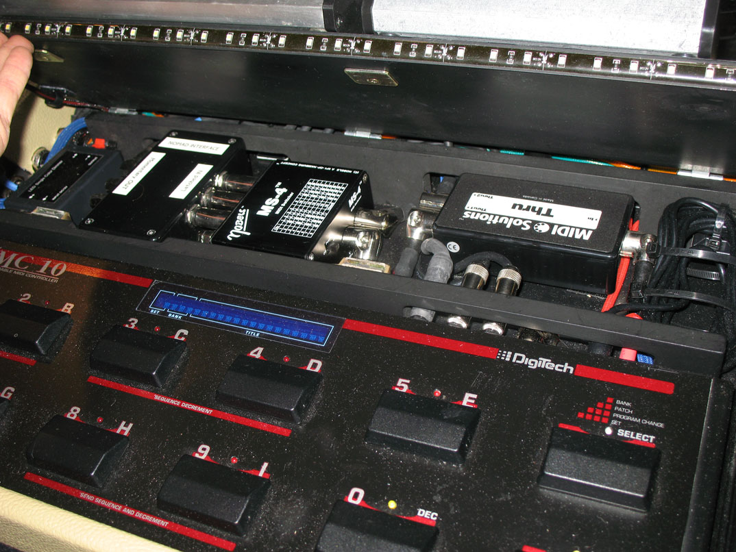
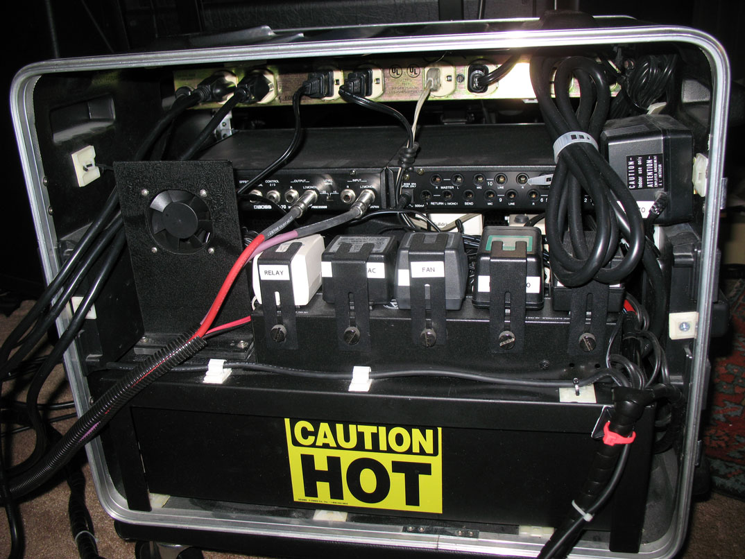
Beneath the hood of the left-hand board. Connectors for power to the boards and control of amp channel switching shown in the lower photo.
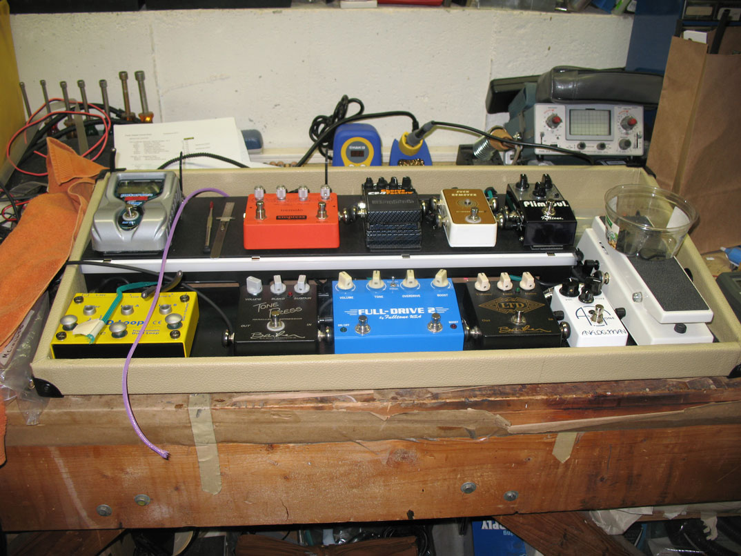
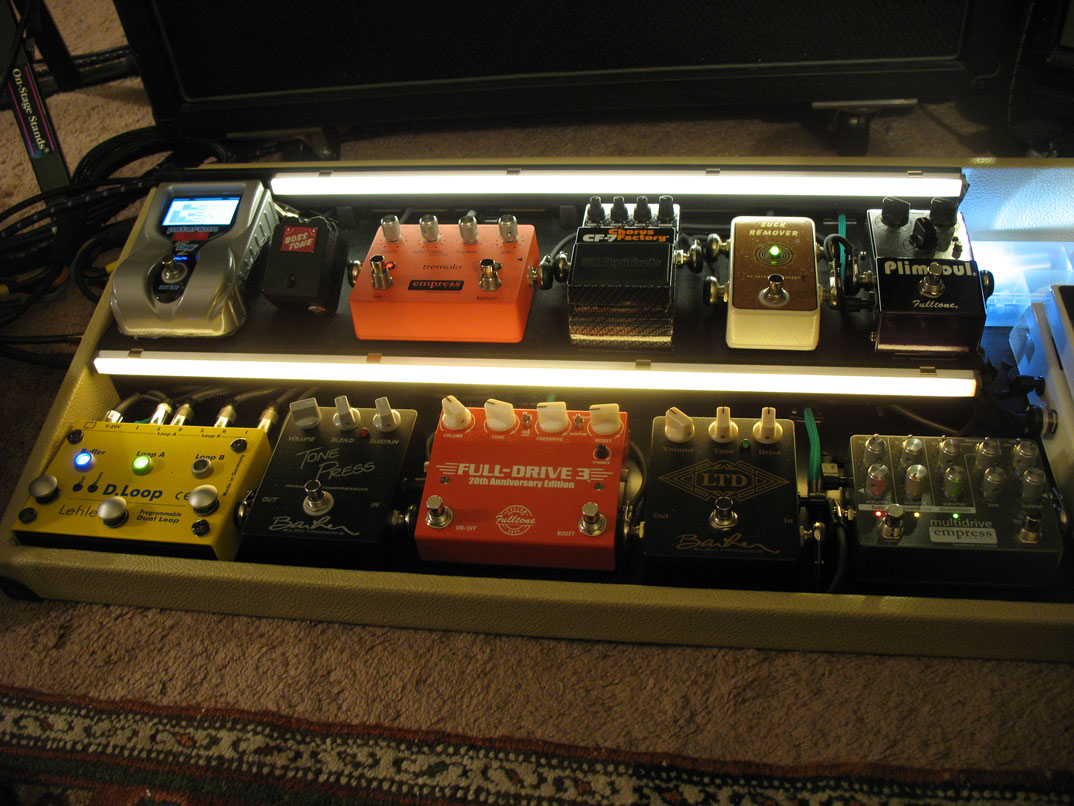
Here is the right-hand board in its final form with a new FD3 pedal, and an Empress Multidrive replacing the AstroTone (top photo). These late entries JUST fit.
Here is the small rack that holds the power supplies for the board. Left: SE-70 Multieffect (used for amp #1), Right: Boss MX-10 line mixer. I plan to add a TC Electronic G-Major II for amp #2. The mixer can be used to mix and route the returns from the two multieffect units to amp #1 and amp #2 for stereo operation.
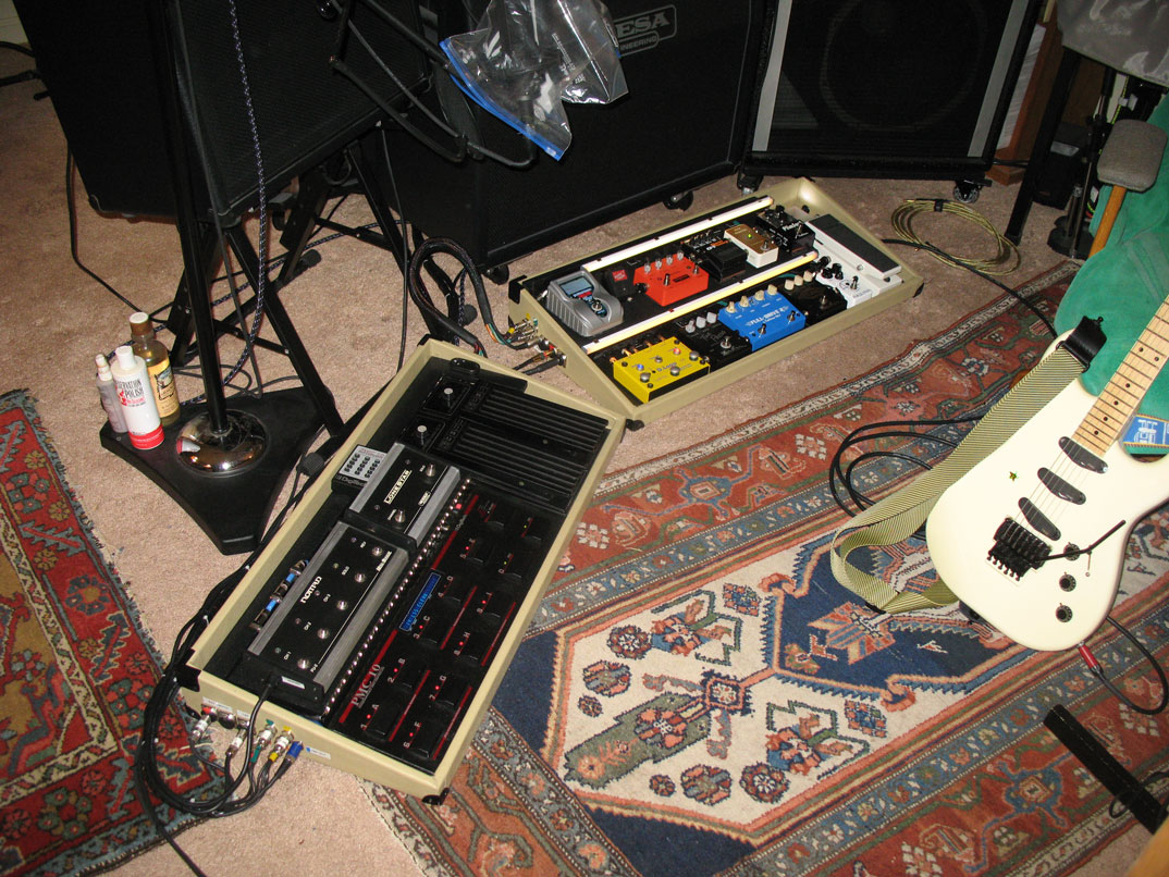
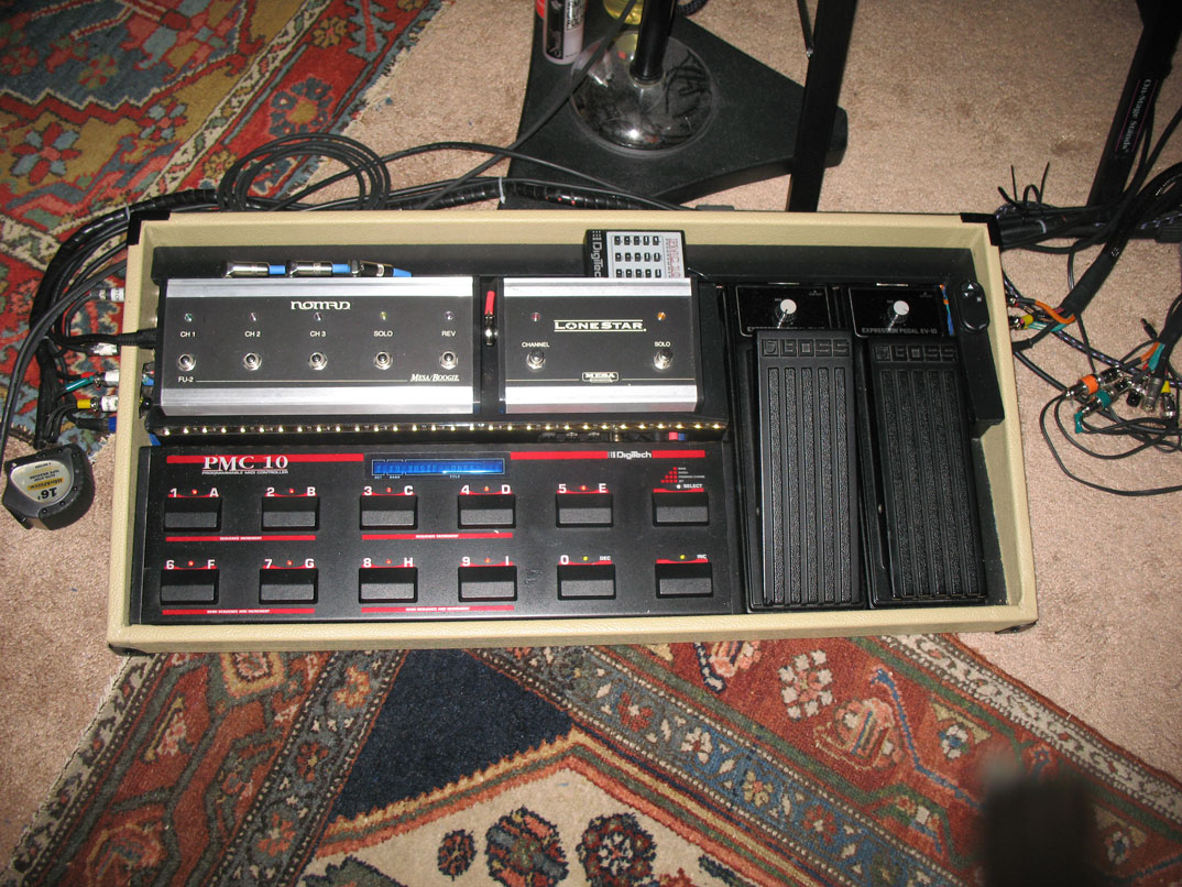
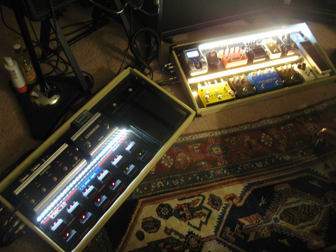
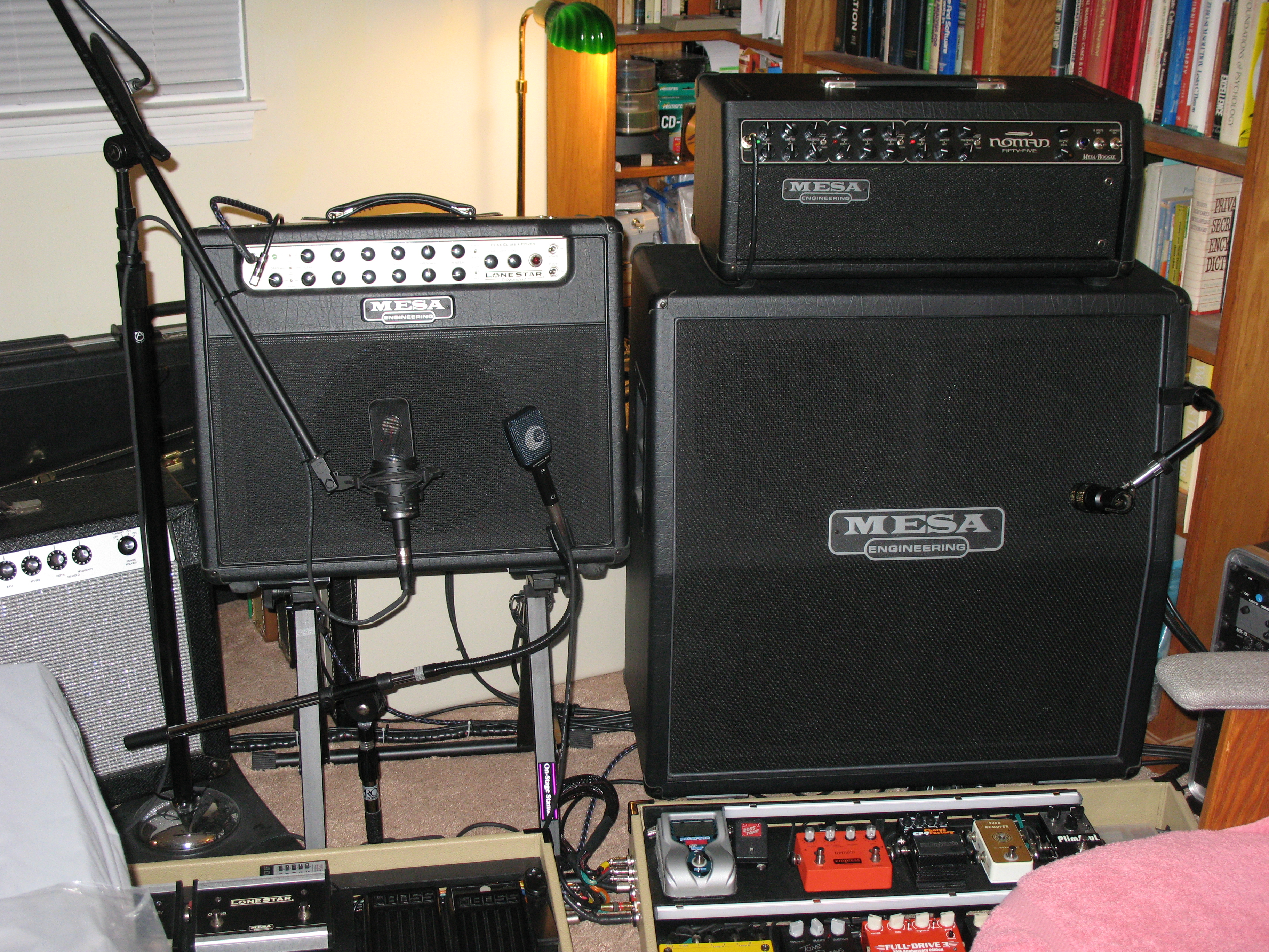
Here is a picture of the pedalboards in Infernal Racket Studio A (aka The Kiddie Boy R&D Lab) : RIGHT, Mesa Nomad; LEFT, Mesa Lone Star Special; FAR LEFT, Gibson Lancer.
I owe thanks to JNEPRO, RACKDOCTOR, Sharbono, Schtaf, Ccouch7, BluesHarp, commercial builders Helweg, Fix Pedalboards, Trailer Trash, and the many other pedalboard builders and equipment fanatics on The Gear Page (thegearpage.net) for the ideas I used.
END