I
bought a Fender Twin Reverb amplifier in the late 70's. It never sounded very good, and occasionally cut out for no apparent reason. For about 25 years the amplifier mostly sat in the closet, until I finally pulled it out to take a closer look at it.
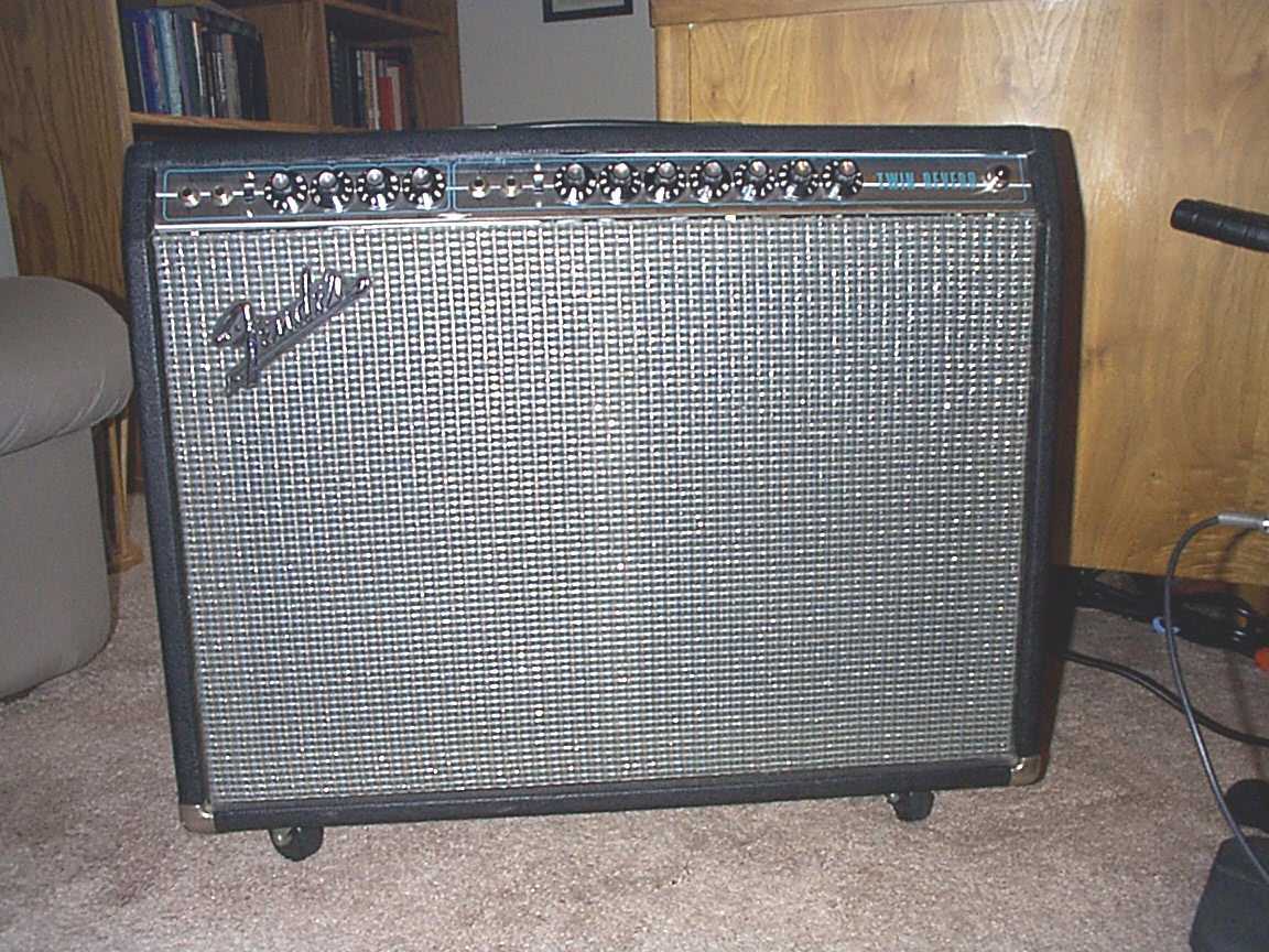
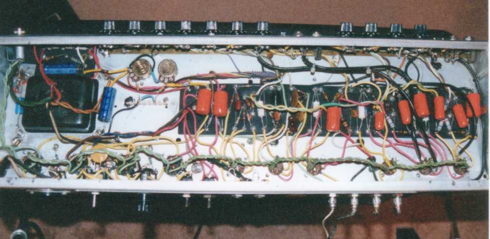
It had RCA tubes, evidently very tired, most of them microphonic. Inside the amp chassis I found "Richard Hand, 1971" stamped near the transformer. The serial numbers on the Utah speakers indicated that they were made in June of a year ending in one, undoubtedly 1971. The filter capacitors looked really old, dried out, and beat.
The amp had the generally disliked AA270 circuit. This can be changed to the earlier ('63) blackface AB763 circuit by removing some capacitors and changing some resistors. The stock wiring was not very neat, and I could only hope that I could correct this enough to keep the amp from oscillating after I removed some of the AA270 bits.
Compared to my other various amplifiers, the amp sounded thin, anemic, with flatulent bass response. I could hear some faint power supply hum when I played low notes, a sure sign of bad filter capacitors. This amp sure sounded nothing like the 1964 blackface Super Reverb or even the AA270 1970 Dual Showman amps that I had once owned and loved.
But would changing component values to BF values actually improve the tone of the amp? Not necessarily, I discovered. Replacing the power supply capacitors fixed the problems, but most of the changes to BF specs made the amp tone too strident and trebly as well as too bass-heavy. Here are the changes I made and what I discovered. Your amp, your tastes and your mileage may vary. The usual cautions about high voltage apply.
Procedure
-
Unplug the amp from the wall outlet. Let it sit for a day or two, or discharge the capacitor before proceeding.
- Carefully remove the tubes, unscrew the chassis bolts, and remove the chassis. Don't forget to unplug the speaker and all cables from the chassis.
-
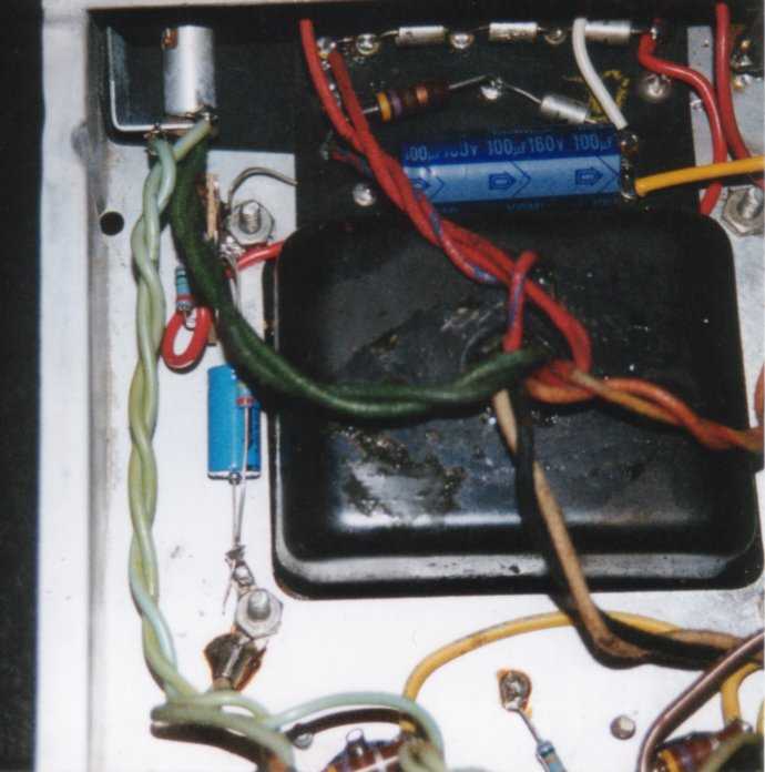
Replace old filter capacitors. Make sure that the filter capacitors are discharged. Remove doghouse lid over the filter capacitors. Replace the capacitors:
|
Quantity |
Old (AA270) |
New (AB763) |
|
3 |
20 mfd, 500 V |
20 mfd, 500 V |
|
2 |
70 mfd, 350 V |
82 mfd, 350 V* |
* Closest value that I found to the desired 70 microfarads.
- Power supply resistors: Leave stock (AA270)!
| Voltage At: | AB763 Schematic | AA769 Schematic | Measured: AA270 Modified to AB763 PS @ 122 VAC | Measured: AA270 @ 122 VAC |
| Point B (after choke) | 458 V | 405 V | 440 V | 448 V |
| Point C (After 1st resistor)* | 450 V | 380 V | 427 V | 420 V |
| Point D (after 2nd resistor)** | 410 V | 315 V | 391 V | 351 V |
| 6L6 Plates | 460 V | 405 V | 443 V | 450 V |
| PI Plates | 245 V | 245 V | 244 V, 240 V | 277 V, 286 V |
| V2 Preamp Plates | 260 V | 210 V | 268 V, 262 V | 237 V, 241 V |
Notes: *1st resistor is 2.2 k-ohm in AA270 & AA769, 1 k-ohm in AB763. **2nd resistor is 10 k-ohm in AA270 & AA769, 4.7 k-ohm in AB763. Amp at idle, volume controls at zero.
Changing the AA270 to AB763 power supply resistors resulted in the voltages shown in the fourth column in my amp. Could these voltages somehow contribute to the strident tone I was hearing after modification of the amp?
As shown in the table above, the AB763, AA270, and nearly identical [to the AA270] have different voltages throughout the power supply and power supply distribution to the preamp, power amp and phase inverter (PI). All three amps apparently have the same power transformers, so what are we to make of this?
Some of the differences can be accounted for by normal resistor tolerance, but my hypothesis is that the line voltages in the USA changed from the early 60's to the early 70's from a nominal 115 VAC to 120 - 126 VAC in much of the country, and that the higher supply resistors in the AA270 were meant to compensate for this. The voltages shown on the AA769 schematic would seem to indicate Fender created the schematic based on mains at a lower line voltage, probably 110 - 115 VAC. However, I suppose it is possible that Fender measured the AB763 schematic voltages with a higher 117 - 120 VAC mains input, contrary to the AA769.
One difference between the AA270 modified to AB763 and the original AA270 that jumps out is the supply voltage to the preamp (V2 shown in the table). A deep search on the web reveals that many amp tinkerers have played around with this voltage, and some report that voltages above 235 V can result in an increase in treble in a Fender BF or SF amp.
I can confirm that going back to the stock AA270 power supply resistors did indeed soften the treble response of my amp a little, so I recommend you leave the power supply stock in your AA270 or AA769 unless you really want MORE treble.
- Tube holders (optional). Remove 6L6 base spring retainers, install coil-spring & cap type retainers (Sovtek or similar). This is a nice touch that helps keep the tubes firmly in their sockets.
-
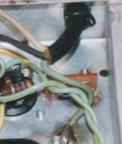
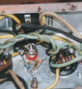
Hum reduction circuit. Optional, but works great to reduce residual hum. Remove two 100 ohm resistors that run from the pilot light to ground, at the ground lug end. Attach a new 3-terminal lug strip to the chassis of the amp. Attach the two resistors to the same terminal of the lug strip, making sure that this terminal is insulated from the chassis ground, then run a 47 mfd capacitor in parallel with a 100 k ohm resistor from the terminal to ground. Connect the negative end of the capacitor to ground. Now connect one end of a 1 meg W resistor to the B+ (high voltage output) of the amp, and connect the other end to the terminal to which you have attached the two 100 ohm resistors. The 1 meg and 100 k resistors form a voltage divider. By attaching the two 100 ohm resistors to the divider at the 100 k resistor, you offset the AC heater voltage (6.3 volts AC) with a DC bias of around 42 volts. This makes any electrons emitted from the tube filaments less likely to influence the grid and show up as hum in the tubes� output signals. The 47 mfd capacitor helps hold the DC offset voltage constant. Note: The resistor values to the right of TR2 are not correct -- I restored these back to stock AA270 values!
-
HV spike protection for power tubes. Add reverse biased diodes to pin 3 of the outside two power tubes, to ground. Use three 1N4007 diodes in series for each tube, or equivalent, so that the total reverse breakdown voltage is 3 kV. Mount the diodes on a small PC board, and tack to the chassis with hot melt glue. This is not an essential modification, but could extend the life of your power tubes.
|
|
|
-
Spike protection for amplifier. Add a 130 volt MOV across the 120 VAC input, across the hot and neutral leads. You may find it convenient to mount the MOV across the ground switch.
-
Bias measurement terminals. Optional. Install "banana plug" or similar binding posts between each pair of 6L6 output tubes by drilling two small holes in the chassis. Install the binding posts on the outside of the chassis, with the wire lugs on the inside, near the output tubes.
-
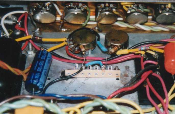
Anti-oscillation capacitors & cathode bias measurement resistors. Remove ground straps from pin 8 of the two outside 6L6 sockets. Remove 2000 pF (.002 uF) capacitors from the inside two 6L6 tubes (pins 8 to 7 and pin 8 to ground). Facing the rear panel of the amp chassis, connect black grounding wires from pin 8 of left pair of 6L6 tubes to red post of banana plug on left side of amp. Run a one ohm precision resistor from the post to ground. Repeat for the right pair and right post. Optional: Add a black binding post wired directly to ground next to the electrolytic bias circuit capacitor. Note: If amp oscillates when volume cranked, it will be necessary to change the routing of the wires, or re-install 2,000 pF capacitors from pin 7 to ground for each pair of tubes. Identifying the source of the oscillation can be a tedious trial-and-error process. Installing smaller value (200 �1,000 pF) anti-oscillation capacitors may work and would allow the amp to retain most of the vintage tone lost from using the 2,000 pF capacitors.
-
Dual bias adjustment circuit. This circuit allows you to set the bias of the four power tubes while retaining the stock bias balance control, which balances the push-pull pairs. You still should buy matched pairs, but you can adjust for pairs that do not match each other exactly. The stock bias balance pot has four terminals. Three of these are conventional potentiometer terminals, that is, two ends of the potentiometer resistance and the wiper. The fourth terminal is a center tap. Follow the wire attached to the center tap to the 50 mfd capacitor and 3.3 k ohm resistor. These supply the bias voltage. Remove the wire, and insert a 5 k ohm linear potentiometer in between the bias supply and center tap of the bias balance potentiometer. You will have to physically attach the 5 k potentiometer to the amp. I drilled a hole to the side of the bias balance potentiometer and inserted the new potentiometer. Set the new potentiometer to its minimum value for now.
-
Reverb output jack. Remove 2000 pF capacitor across 220 k resistor.
-
Phase inverter. Many people modify the AA270 phase inverter to AB763, which involves replacing a handful of resistors. This increases the gain about 2 dB, but reduces headroom and causes what some call a "low fi" distortion, which I doubt you can hear at less than ear-bleed volume levels. I ran simulations of both PIs, and according to the sims, the AA270 balances the two output phases more accurately than the AB763, so I switched from AB763 PI back to stock, replacing all the carbon PI resistors with higher-precision metal film types. To reduce bass flatulence a little, I took the stock PI input coupling capacitor out (.01 mfd) and replaced it with the AB763 value, .001 mfd. Depending on your speaker, you might prefer more bass and want to use the stock value or even a little higher value, but I wanted less bass. Many people like to use a Mallory 150 capacitor in this spot for a [claimed] warmer tone.
-
Optocoupler. Remove 0.002 mfd capacitor across the 10 meg resistor at the optocoupler in the vibrato circuit.
-
Shared preamp cathode circuit. According to Weber, this mod improves the dynamic response of the amp, but I could not hear any improvement. If you run two instruments simultaneously, one into the normal and other into the vibrato channel, I suspect you would hear an improvement with this mod. Disconnect yellow wire running from pin 8 of the next to last tube (near normal input, V2). This wire runs to pin 8 of the last tube (V1). Note that V1B and V2B share the same cathode circuit in the AA270 and AB763. Insert two Fender eyelets in the main circuit board at the extreme edge, near V1. Run the yellow wire from V4A to the nearest eyelet. Connect a 1500 ohm resistor and 10 mfd capacitor in parallel, from this nearest eyelet to the second eyelet, with the negative terminal of the capacitor facing the second eyelet. Run a wire from this nearest eyelet to ground. Larger resistance values will provide higher gain in the normal channel. Higher capacitance values will boost bass, but may result in a flabby or flatulent sound. Follow the red lead from pin 8 of V2 (V2B cathode) to the circuit board, and locate the stock 820 ohm cathode resistor and 25 mfd bypass capacitor. Replace these with 1500 ohm resistor and 10 mfd capacitor. I used non-polarized types here. These are supposed by some to sound better than electrolytics, but this is open to some debate.
-
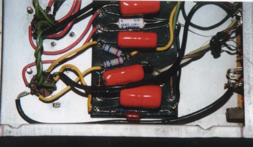
Tone capacitors (optional, but often done). Replace the brown 0.047 uF tone capacitors, commonly referred to as "brown turds," to orange drop polypropylenes. Leave the 0.1 uF tone capacitors in the amp. Replace the 250 pF ceramic treble capacitors (2) with 250 pF silver mica. This is one of those "if it ain't broke, don't fix it" situations. I at first replaced all of the tone capacitors with orange drops, but this seemed to make the amp a little too bright. I doubt that anyone can tell the sound of a single orange drop compared to the stock capacitor it replaces, but changing them all to orange drops might be another matter entirely. I put the original blue capacitors back in, but did in the end yank out the brown turds and replace them with ODs.
-
Vibrato channel second stage coupling capacitor (optional). Replace 0.022 mfd coupling capacitor at the output of the second gain stage of the vibrato channel with an "orange drop" polypropylene capacitor. Orange drops here are not considered to make any discernable difference in tone, but ODs are higher quality than stock.
Normal channel preamp coupling capacitors (optional). Replace 0.047 mfd coupling capacitors between first and second preamp tubes (V1B à V4A) with orange drops.
Potentially noisy resistors in preamps. Change 100 k carbon composition resistor (1 W) on V1 & V2 plates to carbon film, 2 watt (quantity 4).
More coupling capacitors (optional). Replace 200 volt 0.1 mfd capacitor connected to pin 7 of V6 (12AT7 phase inverter tube) with a mylar Xicor.
-
Bright switch capacitors. Just for the heck of it, I experimented with smaller values than the stock 120 pF on the vibrato channel, and wound up using 40 pF silver mica. Even with the lower value, the amp sounds bright enough to me with the bright switch "off," and I rarely use it in the "on" position.
-
Set bias. Measure the power tube plate voltage (should be around 450 V to 460 V), and then measure the voltage to ground at each bias measurement terminal. Adjust the bias (5 k pot) and bias balance until the tubes are at 50 to 65 percent of the rated 25 watts for a 6L6. Since each terminal is connected to a pair of tubes, you have to double everything. For example, a reading of 66.5 mV means you have 66.5 mA (V = IR, R = 1 ohm) through one pair of tubes, or 33.25 mA through one tube. This works out to about 60 percent of 25 watts for two 6L6 tubes running at 450 volts, again using ohms law to do the math.
-
Lead dress. With chassis in operating position, tubes pointing down, pull all signal wires away from the chassis to reduce capacitance to ground. Make sure signal wires cross each other at right angles. Pull all filament heater wires up as far as possible away from all other wires.
-
Line input. I wired the second input jack of the Normal channel to the wiper of the treble control. This bypasses the tone stack and feeds the input directly to the volume control. With this easy to reverse mod, the second input serves as a slave or line input, allowing you to drive the amp from another amp or from a line level outputs from a rack-mounted stereo effect unit.
-
Death capacitor and supply IEC / UL wiring. For safety and conformance to modern electrical codes, make sure that the black wire from the 120 VAC supply line connects to the fuse, and the fuse output connects to the standby switch, and the output of the standby switch to the power transformer. The white / neutral wire should go straight to the other side of the transformer. Make sure that you remove the capacitor on the ground reverse switch, disable the switch (although you can leave it in the amp and even use it as a terminal strip), and make sure that you are using a modern three-prong plug with the chassis connected to ground. This last step should probably be the first thing you do, not the last!
Other Changes Considered or Tried and Reversed Back to Original
Power amp negative feedback circuit. Weber and others suggest that you can add a multi-position switch to let you select among several feedback resistors. A value of 820 ohms is stock AB763. A value of 1650 ohms duplicates a 6G8 Twin, and 820 ohms with a 0.01 mF capacitor copies a late CBS, 135 watt Twin. You may not want to bother with this mod, the tonal changes are very subtle, and not worth the effort, in my opinion. If you add this switch, I suggest that you use the hole for external speaker jack, or place a new hole in a very inconspicuous spot at the rear of the chassis.
Coupling capacitor to reduce excessive bass response. If you would like to reduce the bass response of one of the channels, remove the wire between treble and volume control, and replace with an 0.001 mF � 0.0022 uF capacitor. This is supposed to cut out very low frequency bass, and get rid of any flabby or tubby bass response. I tried a 0.001 uF capacitor in the vibrato channel. The results were a subtle reduction in the bass, but I thought that the midrange tone of the amp suffered, so I changed the amp back to stock.
Reverb mixer capacitor. I substituted a silver-mica for the original 10 pF ceramic, per Weber�s instructions. I thought the sound of the reverb was too bright, so I restored it back to original. Here the crummy original ceramic capacitor seemed to sound the best.
Switch to disable vibrato. Running wires to a switch on the back panel to disconnect the vibrato stage adds more spaghetti to the interior of the amp, and, in my opinion does not make much difference in the tone. One alternative is to install a potentiometer for the vibrato intensity that includes a push-pull or off switch.
High voltage fuse. I added a 1 A fuse between the high voltage supply and the 6L6 output tubes. Eventually I decided that it was not needed and might have a bad effect on the sound of the amp, so I took it out. I honestly believe that the resistance of this fuse contributed to flabby, farty sounding bass response, but I did not do any measurements that can substantiate this.
Star grounding. The grounding scheme used in the AA270 is an apparent disaster. The amp has multiple grounds, including a brass plate under the control panel wired to all the preamp sections. This is an invitation to ground loops and hum. But guess what? My amp is as quiet as a mouse (go figure), so at least for now I have no incentive to re-route all the grounds to a star (nested) ground configuration. The engineers at Fender knew what they were doing.
Finishing Touches
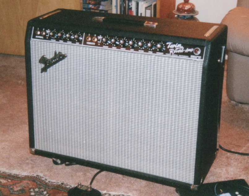
I measured the spacing of the controls on the Reissue Twin Reverb, and the spacing seemed to match my silverface. I decided to order a replacement faceplate to see whether it really would fit on my silverface Twin. When the faceplate arrived, I had to ream the holes out very slightly to allow the pots to fit. The lettering is a bit bolder than on the original blackface front panel, so it would not fool an expert, but the black panel looks great. Next I replaced the silver and blue grill cloth with black and silver to match the blackface era amps. Now I have a good approximation to a blackface in appearance, but not one that would fool an expert, and I have no intention of trying to rip anyone off.
Results
The amp now has a nice classic clean Fender sound, much improved over the tired, anemic, thin sound that I had before, and it looks nice too. Changing the tubes and filter capacitors account for most of the tonal improvement, but a few of the small tweaks I did helped as well.
The circuit in this amp does not depart in any radical way from the AB763 blackface circuit except in the power supply, which is stock silver face to keep the voltages closer to ideal. The DC offset on the heater lines reduces hum, a good thing. The MOV's and spike protection diodes should make the amp more reliable, and have no effect on the tone, as far as I can tell. I could easily restore the shared cathode bias on the preamp tube, but I do not believe this would have much effect on the tone. The orange drop capacitors and silver micas that I kept, while not stock, seem to add a nice little bit of sparkle without making the amp too bright. The stock Utahs sound good, but I think the amp would sound even better through some JBL D-120F's or maybe some Weber speakers or a pair of new Jensen Tornado or Blackbird speakers.
Should you wish to "blackface" your own silverface Fender, let your ears be your guide, not anyone's recommendations. After basic maintenance and safety items, change one thing at a time and listen to the results if you really want to get the best sound out of your amp.
|
Chris Taylor |
|
(508)-881-7054 |